
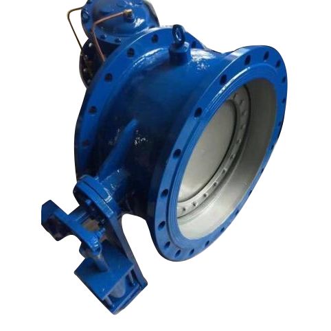
Weir Diaphragm Valve
In demanding industrial environments, fluid leakage and system contamination are not just inconveniences—they are costly risks. The FYL Weir Diaphragm Valve is engineered to bridge the gap between high-precision throttling and long-term durability. By isolating the working parts of the valve from the media, our weir-type design ensures a sterile, leak-proof environment for your most sensitive applications.
Why Global Engineers Trust FYL Valve Solutions
Contamination-Free Operation: The diaphragm provides a hermetic seal, preventing the media from coming into contact with the valve stem and bonnet.
Enhanced Throttling Precision: Designed with a specialized two-piece compressor, our valves allow for micro-adjustments in flow rates that standard valves cannot achieve.
Extended Service Life: By utilizing high-grade elastomers and corrosion-resistant bodies, we reduce the frequency of part replacements.
Technical Excellence in Manufacturing
Our Rigorous Quality Standards
As a leading China manufacturer and supplier, FYL doesn't just assemble valves; we engineer reliability. Every Weir Diaphragm Valve undergoes a multi-stage validation process:
Material Integrity: Sourcing premium alloys and polymers that meet international PN10/PN16 pressure ratings.
Precision Machining: Utilizing CNC technology to ensure the weir (saddle) is perfectly aligned for a bubble-tight shutoff.
Pressure Testing: Every unit is subjected to rigorous shell and seat leak tests before leaving our facility.
Custom OEM Capabilities
We recognize that one size does not fit all. FYL offers tailored OEM services, allowing procurement managers to request specific coating materials or actuator configurations to meet unique project specifications.
Versatile Applications for Modern Industry
Where the FYL Weir Diaphragm Valve Excels
Pharmaceutical & Biotech: Ideal for high-purity water systems where hygiene is non-negotiable.
Chemical Processing: Safely handles clean corrosive liquids and industrial gases.
Water Management: Perfect for treatment plants requiring consistent throttling without the risk of external leakage.
FYL Weir Diaphragm Valve Technical Parameters
| Size (DN) | Size (Inch) | L | D | D1 | D2 | Z-Ød | ||||
|---|---|---|---|---|---|---|---|---|---|---|
| PN10 | PN16 | PN10 | PN16 | PN10 | PN16 | PN10 | PN16 | |||
| 15 | 1/2 | 125 | 95 | 95 | 65 | 65 | 45 | 45 | 4-14 | 4-14 |
| 20 | 3/4 | 135 | 105 | 105 | 75 | 75 | 55 | 55 | 4-14 | 4-14 |
| 25 | 1 | 145 | 115 | 115 | 85 | 85 | 65 | 65 | 4-14 | 4-14 |
| 32 | 1¼ | 160 | 140 | 140 | 100 | 100 | 75 | 75 | 4-18 | 4-18 |
| 40 | 1½ | 180 | 150 | 150 | 110 | 110 | 85 | 85 | 4-18 | 4-18 |
| 50 | 2 | 210 | 165 | 165 | 125 | 125 | 100 | 100 | 4-18 | 4-18 |
| 65 | 2½ | 250 | 185 | 185 | 145 | 145 | 120 | 120 | 4-18 | 4-18 |
| 80 | 3 | 300 | 200 | 200 | 160 | 160 | 135 | 135 | 8-18 | 8-18 |
| 100 | 4 | 350 | 220 | 220 | 180 | 180 | 155 | 155 | 8-18 | 8-18 |
| 125 | 5 | 400 | 250 | 250 | 210 | 210 | 185 | 185 | 8-18 | 8-18 |
| 150 | 6 | 460 | 285 | 285 | 240 | 240 | 210 | 210 | 8-23 | 8-23 |
| 200 | 8 | 570 | 340 | 340 | 295 | 295 | 265 | 265 | 8-23 | 12-23 |
| 250 | 10 | 680 | 395 | 405 | 350 | 355 | 320 | 320 | 12-23 | 12-26 |
Installation and Maintenance Best Practices
Quick Start Guide
To ensure optimal performance, the valve should be installed in a position that allows for complete drainage. Verify that the flange bolts are tightened in a star pattern to distribute pressure evenly across the diaphragm.
Related Products


Hot Products
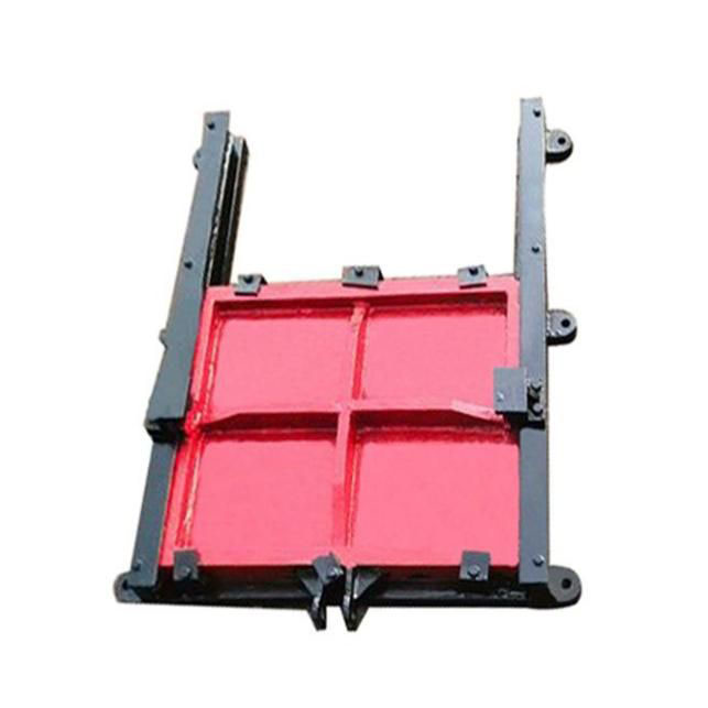
Cast Iron square penstock gate
FYL is a factory which focused on manufacturing different types of cast iron square penstock gate in China, including cast iron square penstock gate, L type single girder gantry crane and so on. Our company available to provide OEM product according to clients require. We welcome both new and old customers, hoping to become your long-term partner in China.
Cast Iron Round And Square Penstock Gate
FYL is a professional cast iron round and square penstock gate manufacturer and supplier in China. Our team has years of industry experience, and support customized production. At the same time, we will also offer you comprehensive service and after-sale service, welcome to contact with us now.
Circulating Mechanical Bar Screen
FYL is a manufacturer and supplier specializing in the production of circulating mechanical bar screens. The company has been established for more than ten years and has formed a complete production line. It continues to innovate and always takes customer needs as the criterion. It supports customized design and production to provide you with products that are more in line with personalized and actual needs.
Double Flanged Bend 45º Ductile Iron Pipe Fittings
FYL is a reliable manufacturer specializing in produce Double Flanged Bend 45º Ductile Iron Pipe Fittings in China. Factory available to produce different type of Ductile iron pipe fittings. Products popular in domestic and export to many countries. Looking forward to becoming your partner and serving you sincerely.
Double Flanged Anchoring With Puddle Flange Ductile Iron
FYL is a reliable Double Flanged Anchoring With Puddle Flange Ductile Iron manufacturer specializing in produce Double flanged anchoring with puddle flange in China. Factory available to produce different type of Ductile iron pipe fittings. Products popular in domestic and export to many countries. Looking forward to becoming your partner and serving you sincerely.
Metal Seat Gate Valve
FYL is a reliable Metal Seat Gate Valve manufacturer in China with a complete range of products and many styles. The FYL Metal Seat Gate Valve is designed with compact structure, stable sealing performance, and flexible operation. As a professional Metal Seat Gate Valve factory and supplier in China, we focus on quality improvement, cost control, and long-term customer value.
- Related Blog
- Reviews