Tilting Disc Check Valve
Tilting Disc Check Valve: Precision Flow Management for Critical Systems
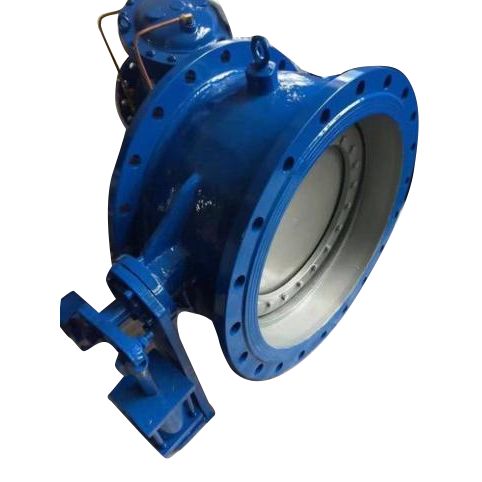
The tilting disc check valve stands as a cornerstone in modern pipeline engineering, delivering dependable unidirectional flow with minimal pressure loss. Designed around a pivoting disc mechanism, it responds instantly to flow cessation, slamming shut before reverse flow can establish. This inherent quick-closing action mitigates water hammer, protecting pumps, compressors, and sensitive instrumentation. Our range includes two primary configurations tailored to diverse installation demands: the space-efficient Wafer tilting type check valve that sandwiches directly between mating flanges, ideal for tight layouts and lightweight piping, and the heavy-duty Flanged tilting disc check valve with integral flanges, offering superior sealing integrity for high-pressure, high-temperature, or large-diameter services. Both variants leverage a streamlined flow path and a low-inertia disc to achieve cracking pressures as low as 0.5 psi (0.034 bar), making them a premier choice for HVAC, water treatment, oil & gas, and chemical processing sectors where backflow prevention and energy efficiency are paramount.
The Tilting Disc Check Valve operates through a carefully balanced disc that rotates on a shaft positioned above the seat centerline. This geometry ensures that even at extremely low flow velocities, the disc lifts smoothly, offering full-area flow with minimal turbulence. Upon flow stoppage or reversal, gravity and reverse flow combine to force the disc against the seat instantly, achieving bubble-tight shutoff. The valve’s short face-to-face dimension simplifies retrofitting into existing piping, while the top-entry design in many sizes permits in-line maintenance without removing the valve body. Enhanced with replaceable seat rings and a shaft sealing arrangement that prevents external leakage, the Tilting Disc Check Valve is engineered for decades of trouble-free operation. Typical applications include pump discharge lines, cooling water circuits, steam condensate return, and compressed air systems where silent, non-slam performance directly impacts system reliability and total ownership costs.
Design Features at a Glance
- Low-inertia tilting disc for rapid, non-slam closure and water hammer elimination
- Full-ported body minimizes pressure drop across the valve
- Two basic body styles: wafer (compact, lightweight) and flanged (rigid connection)
- Shaft positioned above seat centerline, enabling gravity-assisted sealing
- Metal or resilient seated options for temperatures from -196°C to +550°C
- Replaceable seat rings and accessible disc/shaft assembly for simplified maintenance
- Short face-to-face dimensions per API 594 and ASME B16.10
- Bi-directional tightness possible with optional soft seat inserts
- Available with counterweight or spring-assist for special flow conditions
- Corrosion-resistant materials: stainless steel, duplex, super duplex, Hastelloy, titanium, and more
Standard Technical Specifications
| Parameter |
Wafer Type |
Flanged Type |
| Nominal Diameter |
2" – 48" (DN50 – DN1200) |
2" – 60" (DN50 – DN1500) |
| Pressure Rating |
Class 150 – Class 600 |
Class 150 – Class 2500 |
| Face-to-Face |
API 594 (Short/Long Pattern) |
ASME B16.10 (Short/Long Pattern) |
| Design Standard |
API 594, API 6D, ASME B16.34 |
API 6D, ASME B16.34, BS 1868 |
| End Connection |
Wafer (between flanges) |
Raised Face (RF), RTJ |
| Leakage Class |
API 598 Zero Leakage |
API 598 Zero Leakage |
| Temperature Range |
-29°C to +425°C (standard) |
-196°C to +550°C (extended) |
| Operation |
Automatic (flow/pressure actuated) |
Automatic, optional counterweight |
Typical Materials of Construction
| Component |
Standard Material Options |
| Body |
Carbon Steel WCB, LCB, CF8M (316 SS), CF8 (304 SS), Duplex 4A/5A, Hastelloy C276 |
| Disc |
316 SS, 304 SS, Duplex SS, Monel, Titanium Grade 2 |
| Shaft/Pin |
17-4PH SS, Inconel 718, 316 SS |
| Seat Ring |
Metal (Stellite overlay, 316 SS), PTFE, RPTFE, PEEK, Devlon |
| Seal/Gasket |
Spiral-wound SS/Graphite, PTFE, Graphite |
| Bushing/Bearing |
PTFE-impregnated SS, RPTFE, Bronze |
Performance Data and Cv Values (Example – Wafer Type, 150 Class)
| Valve Size (inch) |
Cv (US gpm @ 1 psi ΔP) |
Approx. Weight (lbs) |
| 2" |
95 |
12 |
| 4" |
430 |
38 |
| 6" |
980 |
72 |
| 8" |
1,850 |
130 |
| 10" |
2,950 |
210 |
| 12" |
4,300 |
310 |