
Ductile Iron Double Flanged 90° Duckfoot Elbow
When designing robust and efficient drainage and sewer systems, selecting the right fittings is paramount for ensuring longevity, structural integrity, and optimal flow. The Ductile Iron Double Flanged 90° Duckfoot Elbow stands as a superior solution for redirecting wastewater flows in pressurized and non-pressurized systems. This specialized fitting combines the inherent strength and corrosion resistance of ductile iron with a unique offset "duckfoot" base, providing exceptional stability and preventing settlement in trench applications. It is engineered for direct, flanged connection to pipes, facilitating easy installation and maintenance. For projects requiring precise 90-degree directional changes with enhanced support, our Double Flanged 90 Degree Duckfoot Bend Ductile Iron Pipe Fittings offer reliable performance. Similarly, systems needing a compact turn can benefit from a Ductile Iron Double Flanged Short Radius 90° Bend, while the versatile Double Duck Foot Flanged Bend provides an alternative configuration for specific layout requirements.
The Ductile Iron Double Flanged 90° Duckfoot Elbow is manufactured to exacting international standards, ensuring compatibility and reliability in municipal, industrial, and commercial infrastructure. Its design features a double-flanged configuration at both ends, allowing for secure bolting to adjoining flanged pipes or valves, creating a rigid, leak-resistant joint. The integral duckfoot base extends the footprint of the fitting, distributing load more evenly across the bedding material and significantly reducing the risk of point loading and subsequent pipe movement or joint stress. This makes it particularly suitable for installations in unstable soils or areas with high traffic loads. The interior surface is typically cement-mortar lined for sustained hydraulic capacity and corrosion protection, while the exterior is coated with a protective layer, often epoxy, to resist aggressive soil conditions.
Key Specifications & Dimensions
- Material: High-grade Ductile Iron (DI) conforming to ISO 2531 / EN 545 / EN 598 / ASTM A536.
- Pressure Rating: Designed for PN10, PN16, or PN25 pressure classes, suitable for both gravity and pressure systems.
- Corrosion Protection: Standard internal cement mortar lining and external epoxy coating. Alternative linings (e.g., polyurethane) and coatings (e.g., zinc) available upon request.
- Flange Standard: Drilled according to ISO 7005-2 or ASME B16.1, ensuring global interchangeability.
- Application: Primarily used in sewer mains, stormwater systems, industrial waste lines, and water transmission pipelines requiring a stable directional change.
| Nominal Diameter (DN) | Approx. Center to Flange (A) mm | Approx. Base Length (B) mm | Approx. Height (H) mm | Flange Diameter (D) mm | Approx. Weight (kg) |
|---|---|---|---|---|---|
| 100 | 220 | 400 | 300 | 215 | 18.5 |
| 150 | 250 | 450 | 350 | 280 | 28.0 |
| 200 | 300 | 500 | 400 | 335 | 45.0 |
| 250 | 350 | 550 | 450 | 405 | 68.0 |
| 300 | 400 | 600 | 500 | 460 | 95.0 |
| 400 | 520 | 750 | 620 | 580 | 165.0 |
| 500 | 650 | 900 | 750 | 715 | 285.0 |
Note: Dimensions and weights are approximate and may vary slightly based on manufacturing standards and pressure class. All products undergo rigorous hydrostatic testing and quality inspections to guarantee performance.
Related Products


Hot Products
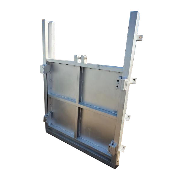
Stainless Steel Penstock Gate Channel Type
FYL is a stainless steel penstock gate channel type manufacturer from China. We have our own factory. After more than ten years of development, we integrate design, production and sales to provide you with high-quality products, comprehensive services and preferential prices. This gate is mainly suitable for water treatment, power stations, hydraulic devices and other scenes. The material and specifications can be customized according to your needs.
Double Girder Gantry Crane
Double girder gantry crane is a special equipment. FYL's factory has been producing and manufacturing this type of equipment and various water conservancy equipment for more than ten years. We have rich experience and a professional team that is very reliable. We accept customized requirements, please feel free to contact us.
L Type Single Girder Gantry Crane
FYL is engaged in the manufacture and sales various L Type Single Girder Gantry Crane in China. Our equipment has advanced technological processes and quality control systems, it can be customized according to customer needs to provide customers with high-quality, safe and reliable gantry cranes.
Double Flanged Anchoring With Puddle Flange Ductile Iron
FYL is a reliable Double Flanged Anchoring With Puddle Flange Ductile Iron manufacturer specializing in produce Double flanged anchoring with puddle flange in China. Factory available to produce different type of Ductile iron pipe fittings. Products popular in domestic and export to many countries. Looking forward to becoming your partner and serving you sincerely.
Floating Ball Valve
FYL is a large manufacturer for industry machine in China. Our factory produce different type of ball valves fill in all international standards. Floating ball valve is one of top sell valves. Our company focus on improving quality, reducing production costs, and benefiting customers. We look forward to becoming your partner and serving you sincerely.
Ductile Iron Wafer butterfly valve with Handle
A high-quality Ductile Iron Wafer Butterfly Valve with Handle, manufactured by the FYL factory in Tianjin, China. This product features a valve body constructed from high-strength, corrosion-resistant ductile iron, combined with a lightweight and compact wafer-style structure. This design not only conserves installation space but also delivers superior sealing performance and precise fluid control. Operated via a manual handle, the valve allows users to easily regulate the flow of various media, including water, oil, and gas.
- Related Blog
- Reviews