
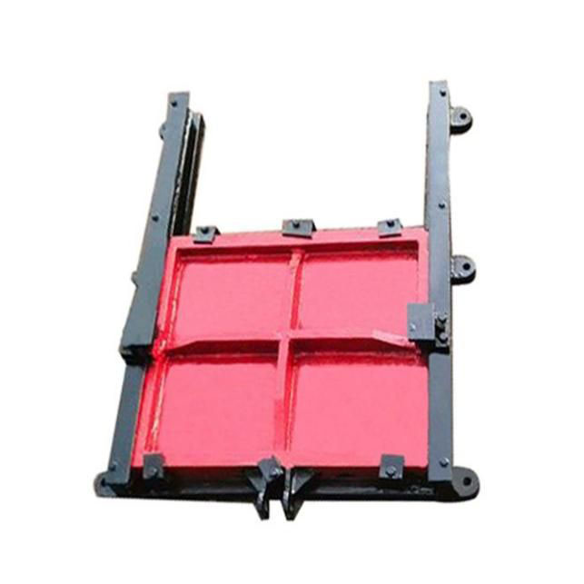
Double Flange Limited Expansion Joint
In industrial piping systems, managing thermal expansion, vibration, and misalignment is critical for safety and longevity. This is where the Double Flange Expansion Joint proves indispensable. Specifically engineered for controlled movement, our Double Flange Limit Expansion Joint is a superior solution for applications requiring precise axial compensation with built-in restraint to prevent over-extension. Unlike basic compensation units, this model integrates positive stop mechanisms, ensuring the pipe system remains secure under pressure fluctuations and temperature cycles. For systems needing axial movement absorption with straightforward flange-to-flange installation, the Double Flange Telescopic Expansion Joint offers an efficient and reliable alternative. Our products are designed to mitigate stress on anchors and guides, reducing maintenance costs and preventing premature system failure.
The Double Flange Limited Expansion Joint is manufactured to exacting standards, utilizing premium materials to ensure durability in demanding environments. Key to its performance is the precision-engineured telescopic sleeve assembly, which allows for smooth axial travel while maintaining a leak-tight seal. The integral limit rods, typically constructed from high-tensile steel, are a defining feature. These rods are designed to absorb the thrust forces generated by internal pressure, transferring this load to the pipe anchors and effectively preventing joint over-extension. This design not only protects the joint's bellows but also safeguards the entire piping structure. The flanges are machined to industry-standard specifications, ensuring a perfect bolt-to-bolt match with your existing pipeline flanges for a hassle-free installation. The construction typically involves a stainless steel bellows (often 304 or 316 grade) for excellent corrosion resistance, complemented by carbon steel or stainless steel flanges and hardware. Internal liners are frequently incorporated to reduce flow turbulence and protect the bellows from abrasive media, while external covers shield the assembly from environmental damage. The following tables detail the standard specifications and pressure-temperature ratings.
Standard Construction Materials
| Component | Standard Material | Alternative Options |
|---|---|---|
| Bellows | AISI 304 Stainless Steel | AISI 316, Inconel 625 |
| Flanges | Carbon Steel (A105) | Stainless Steel 304/316, Duplex |
| Limit Rods | Carbon Steel w/ Zinc Plating | Stainless Steel |
| Liner (Internal Sleeve) | AISI 304 Stainless Steel | Optional |
| Cover (External Shroud) | Galvanized Steel | Stainless Steel, Aluminum |
Pressure & Temperature Ratings
| Nominal Size (inches) | Max Allowable Pressure (PSI) | Temperature Range (°F) | Standard Axial Movement (± inches) |
|---|---|---|---|
| 2" - 6" | 275 | -20 to +400 | 0.75 - 2.0 |
| 8" - 14" | 150 | -20 to +400 | 1.5 - 3.0 |
| 16" - 24" | 150 | -20 to +400 | 2.0 - 4.0 |
| 26" - 36" | 75 | -20 to +400 | 2.5 - 5.0 |
Key Design Features & Benefits
- Positive Stops (Limit Rods): Absorb pressure thrust and prevent over-extension, protecting system anchors.
- Full Flange Design: Facilitates direct bolting to mating pipe flanges, simplifying installation and maintenance.
- Multi-Ply Bellows: Provides enhanced flexibility and cycle life for long-term reliability.
- Internal Flow Liner: Reduces erosion from turbulent media and minimizes pressure drop.
- External Cover: Shields bellows from mechanical damage and environmental corrosion.
- Versatile Material Selection: Can be customized for corrosive, high-temperature, or other special service conditions.
- Compact Design: Requires minimal space for installation compared to piping loops.
Related Products


Hot Products

L Type Single Girder Gantry Crane
FYL is engaged in the manufacture and sales various L Type Single Girder Gantry Crane in China. Our equipment has advanced technological processes and quality control systems, it can be customized according to customer needs to provide customers with high-quality, safe and reliable gantry cranes.
Double Flanged 90ºDuckfoot Bend Ductile Iron Pipe Fittings
FYL is a reliable manufacturer specializing in produce Double Flanged 90ºDuckfoot Bend Ductile Iron Pipe Fittings in China. Factory available to produce different type of Ductile iron pipe fittings. Products has good price and high quality. Looking forward to becoming your partner and serving you sincerely.
Tilting Butterfly Type Check Valve Without Hydraulic
As a reliable industrial valve manufacturer, FYL can provide tilting butterfly type check valve without hydraulic. This valve can operate autonomously, has low resistance to fluid, and effectively improves efficiency. As a professional factory, we will accompany you with professional services throughout the process, and provide preferential prices and timely delivery.
Pneumatic Gate Valve
FYL is factory located in Tianjin China. Factory specialized in producing different type of valves. Pneumatic Gate Valve is one of major products. Our products has good quality and price advantage, also company available to make OEM products. Welcome inquiries from all over the world.
Rising Stem Metal Seat Gate Valve
FYL is a Chinese factory that can produce different types of valves, including rising stem metal seat gate valve. From the establishment to now, we have more than ten years of industry experience, and always put product quality and customer needs in an important position. We can produce OEM products and provide you with factory prices, high cost performance.
OSY Resilient Seated Gate Valve With Grooved Ends
FYL is factory located in Tianjin China. Factory specialized in producing different type of valves. Grooved gate valve is one of major products. Our products has good quality and price advantage, also company available to make OEM products. Welcome inquiries from all over the world. The OSY Resilient Seated Gate Valve With Grooved Ends is a specialized type of gate valve used in various industrial and fire protection systems. It features an outside stem and yoke, meaning the valve's stem is exposed outside the valve body and moves up and down when the valve is operated. The valve has a resilient seat, typically made of rubber or elastomer, which helps provide a tight seal. The grooved ends make installation easier and faster by allowing mechanical couplings to connect the valve to a grooved piping system.
- Related Blog
- Reviews