
China Circular And Rectangular Cast Iron Sluice Penstock Valve Manufacturers, Suppliers, Factory
For reliable flow isolation and regulation in municipal wastewater networks, industrial water treatment, and flood control gates, our portfolio features the proven Cast Iron Round And Square Penstock Sluice Gate. This gate series integrates seamlessly with the wider range of circular and rectangular cast iron sluice penstock valves, offering a uniform material specification and sealing philosophy. The cast iron body and wedge are moulded to exacting tolerances, then the guide slots and seat faces are machined in a single setup to guarantee tight shut-off. Flange drillings follow DIN, BS, and ANSI patterns, allowing direct bolting into concrete wall thimbles, existing pipework, or custom adapter spools. A bronze or stainless steel stem nut minimizes operating torque, and the optional thrust bearing reduces force required on the handwheel by up to thirty percent.
The Circular And Rectangular Cast Iron Sluice Penstock Valve is supplied with a fusion-bonded epoxy coat that resists microbiologically induced corrosion in anaerobic chambers. Its yoke and stem design accepts a full range of actuation, from basic manual handwheels and bevel gearboxes to multi-turn electric actuators, pneumatic cylinders, and hydraulic rams. Every assembly is pair-tested with its mating gate, and the resilient EPDM or NBR seal performs reliably from 1 °C up to 80 °C without permanent set. T-slot bolts and clamping bars hold the seal profile in place, enabling field replacement without removing the bonnet. Lifting eyes and integral cast-in feet simplify rigging and mounting in both dry and wet installation pits.
Standard Construction Features
- Body and bonnet: Grey cast iron grade EN-GJL-250 (GG25) per ISO 185, surface finished with 250–350 µm solvent-free epoxy.
- Wedge: Solid cast iron with replaceable EPDM wedge-faced seal, full-contact dovetail retention.
- Guide system: Integral cast guide rails, fully machined, with adjustable bronze or UHMWPE wear pads to eliminate shimmy under flow.
- Stem: Stainless steel 1.4021 (martensitic) or 1.4301 (austenitic), rolled threads to reduce notch sensitivity, fitted with a stem guard if requested.
- Stem nut: Dezincification-resistant brass or aluminium bronze, lubricated for life with food-grade grease.
- Packing: Graphite-impregnated PTFE braided rings, externally adjustable gland.
- Limit stops: Mechanical end stops built into the yoke to prevent over-travel in both open and close directions.
| Technical Parameter | Circular Penstock Valve | Rectangular Penstock Valve |
|---|---|---|
| Nominal bore / opening | DN 150 – DN 2000 (larger upon review) | 200 x 200 mm to 2000 x 2000 mm (custom aspect ratios available) |
| Rated working pressure (upstream) | PN 6 bar (87 psi) standard; PN 10 bar (145 psi) optional for wall-mounted units | PN 4 bar (58 psi) standard; reinforced frame available for 6 bar |
| Sealing direction | Uni-directional or bi-directional on request | Uni-directional; bi-directional retrofitable with double seal |
| Leakage rate | Class A (EN 12266-1) / zero visible leakage | Class A (EN 12266-1) / zero visible leakage |
| Stem and nut minimum hardness | Stem 450 HB, nut 200 HB (aluminium bronze) | Stem 450 HB, nut 180 HB (brass) |
| Design standard | AWWA C501 / BS 7775 / DIN 19569 | BS 7775 / DIN 19569, plus client’s water-project specifications |
| Face-to-face dimension | Per EN 558 series 14 (short pattern) | Custom based on wall opening; minimum flange width 180 mm |
| Coating specification | RAL 5015 blue fusion-bonded epoxy, 250 µm DFT minimum, tested for holiday detection at 1500 V | Same as circular; alternative colours and high-build systems on request |
| Operating temperature range | -10 °C to +80 °C (extended -30 °C with optional impact-tested castings) | -10 °C to +70 °C |
Every cast iron sluice penstock valve undergoes a sequence of factory tests recorded on a 3.1 material certificate. Shell strength is verified with a 1.5-times-rated-pressure hydrostatic test for three minutes, and seat tightness is checked at 1.1 times rated pressure with air or water. Functional cycling tests confirm that the wedge travels the full stroke without binding, and the handwheel rim pull does not exceed 360 N for manually operated units. The drive train is sized so that maximum stem stress remains below 25% of the material yield strength at design pressure.
These valves suit sedimentation basins, clarifier inlets, aeration tank isolation, stormwater retention tunnels, and submerged outfall gates. Installation options include wall mounting with spigot-back frame, above-floor pedestal mounting, or open-channel guide frames cast into secondary concrete. An integral stem cover tube protects exposed rising stems in outdoor locations, while the non-rising design eliminates the need for a stem bonnet altogether. Anchor bolt sets are included, and leveling screws allow field alignment of the frame within ±2 mm before grouting.
Related Products


Hot Products

Double Flanged 90ºDuckfoot Bend Ductile Iron Pipe Fittings
FYL is a reliable manufacturer specializing in produce Double Flanged 90ºDuckfoot Bend Ductile Iron Pipe Fittings in China. Factory available to produce different type of Ductile iron pipe fittings. Products has good price and high quality. Looking forward to becoming your partner and serving you sincerely.
Large Size Resilient Seat Gate Valve
Tianjin Fuyaolai Technology Co., Ltd. (FYL) is a premier manufacturer specializing in the Large Size Resilient Seat Gate Valve , offering a comprehensive range of styles and standards (DIN, ANSI, BS, JIS). Our valves are engineered using high-strength ductile iron and advanced vulcanization technology to ensure a 100% leak-proof seal and an extended service life.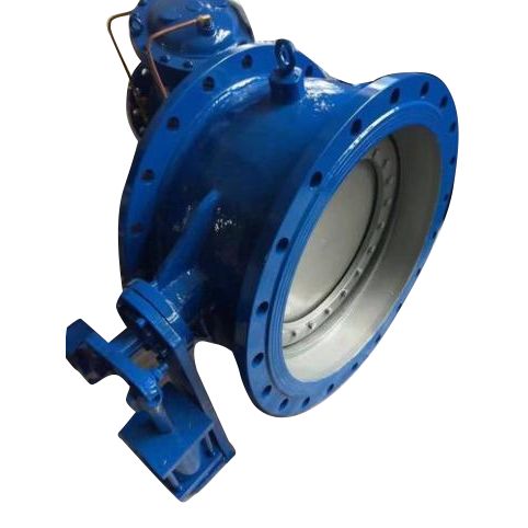
Tilting Type Check Valve
FYL's tilting type check valve is a high-quality product with a compact overall design, which is very convenient to install and use. We have rich experience in the design and manufacture of hydraulic machinery and equipment. Professionals will also conduct strict tests on the sealing of the products to ensure that the valve is leak-free.
Fully Enclosed Rubber Joint
FYL is a comprehensive water conservancy equipment manufacturer with a wide range of products, including fully enclosed rubber joint. This is a pipe system connector made of high-quality rubber material with excellent sealing performance. At the same time, we also strengthen its anti-oxidation and anti-corrosion properties during production to extend its service life. If you have specific needs, you can contact us immediately to get the latest quotation and customized service support.
Basket Filter
FYL is a water conservancy machinery and equipment manufacturer located in Tianjin, China. Basket filter is one of the products we can provide you with. We can provide you with a wide range of products, and we have been working hard to find breakthroughs based on traditional production, supporting customized design and production, and striving to become your long-term partner in China.
OSY Resilient Seated Gate Valve With Grooved Ends
FYL is factory located in Tianjin China. Factory specialized in producing different type of valves. Grooved gate valve is one of major products. Our products has good quality and price advantage, also company available to make OEM products. Welcome inquiries from all over the world. The OSY Resilient Seated Gate Valve With Grooved Ends is a specialized type of gate valve used in various industrial and fire protection systems. It features an outside stem and yoke, meaning the valve's stem is exposed outside the valve body and moves up and down when the valve is operated. The valve has a resilient seat, typically made of rubber or elastomer, which helps provide a tight seal. The grooved ends make installation easier and faster by allowing mechanical couplings to connect the valve to a grooved piping system.
- Related Blog
- Reviews