

How Are Air Valves Applied Across Industrial Fluid Control Systems?
Abstract
Air Valves are critical control components used in pressurized and non-pressurized fluid systems to regulate, release, or admit air during pipeline operation. This article provides a comprehensive technical examination of Air Valves, focusing on structural design, operational parameters, application logic, and system-level integration. Through a structured, question-driven approach, the discussion clarifies how Air Valves function within modern industrial environments and why correct specification and selection directly affect system stability, safety, and long-term performance.
Outline
- Product Overview and Technical Positioning
- Key Parameters and Engineering Specifications
- How Do Air Valves Perform in Real-World Applications?
- Common Air Valve Questions and Practical Answers
Table of Contents
- 1. Product Overview and Technical Positioning
- 2. Key Parameters and Engineering Specifications
- 3. How Do Air Valves Perform in Real-World Applications?
- 4. Common Air Valve Questions and Practical Answers
1. Product Overview and Technical Positioning
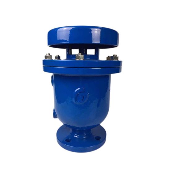
An Air Valve is a mechanical device designed to manage the presence of air within fluid transmission systems. During pipeline filling, draining, or steady-state operation, air accumulation or vacuum conditions can compromise efficiency and structural integrity. Air Valves are installed at strategic points—such as high elevations, pump outlets, and long horizontal runs—to maintain controlled air behavior within the system.
The central purpose of this article is to explain how Air Valves contribute to stable system operation by addressing air-related challenges that commonly arise in water supply networks, industrial processing lines, HVAC circulation systems, and chemical transport pipelines. Emphasis is placed on engineering logic rather than promotional language, aligning with professional procurement and specification practices.
From a structural standpoint, Air Valves typically consist of a valve body, float mechanism, sealing interface, and discharge orifice. These elements interact dynamically in response to pressure changes, enabling automatic air management without external control inputs.
2. Key Parameters and Engineering Specifications
Accurate parameter definition is essential when selecting an Air Valve for industrial use. The following table summarizes commonly referenced technical specifications that influence compatibility and performance.
| Parameter | Typical Range | Engineering Significance |
|---|---|---|
| Nominal Diameter (DN) | DN15 – DN300 | Determines air discharge capacity and pipeline compatibility |
| Pressure Rating | PN10 / PN16 / PN25 | Defines maximum allowable operating pressure |
| Body Material | Ductile Iron / Stainless Steel | Affects corrosion resistance and service life |
| Seal Material | EPDM / NBR / Viton | Ensures tight closure under varying temperatures |
| Operating Temperature | -10°C to 120°C | Indicates suitability for different fluid environments |
| Connection Type | Flanged / Threaded | Impacts installation method and maintenance access |
These parameters should be evaluated in relation to system flow rates, elevation profiles, and transient pressure conditions. Oversizing or undersizing an Air Valve can lead to inefficient air release or unintended pressure fluctuations.
3. How Do Air Valves Perform in Real-World Applications?
Air Valves are deployed across multiple industrial sectors, each presenting unique operational challenges. Understanding application-specific behavior is essential for correct integration.
In municipal water transmission systems, Air Valves are positioned at pipeline high points to release trapped air during filling cycles. This prevents flow restriction and minimizes the risk of air-induced pressure surges. During draining operations, the same valves admit air to avoid vacuum formation that could collapse pipe walls.
Within industrial process pipelines, Air Valves support consistent flow behavior by stabilizing internal pressure profiles. Systems transporting chemicals, cooling water, or treated effluents rely on predictable air management to protect pumps, meters, and control instruments.
HVAC circulation loops represent another critical application area. Air entrainment in closed-loop heating and cooling systems can reduce heat transfer efficiency and increase energy consumption. Properly specified Air Valves allow continuous venting without manual intervention, supporting long-term operational stability.
Across these scenarios, performance is determined not only by valve design but also by installation location, maintenance accessibility, and compatibility with upstream and downstream components.
4. Common Air Valve Questions and Practical Answers
How does an Air Valve automatically release air during pipeline filling?
When a pipeline is initially filled, large volumes of air are displaced by incoming fluid. The Air Valve remains open due to the absence of internal pressure, allowing air to escape freely. As fluid reaches the valve chamber, the float rises and seals the orifice, transitioning the system to pressurized operation.
How is air admitted into the system during pipeline draining?
During draining or sudden flow stoppage, internal pressure can drop below atmospheric levels. The Air Valve responds by opening its inlet path, allowing external air to enter and equalize pressure, thereby preventing vacuum-related structural damage.
How does improper Air Valve selection affect system reliability?
Incorrect sizing or pressure rating can lead to incomplete air release, excessive leakage, or delayed response to pressure changes. These issues may manifest as noise, vibration, inaccurate flow readings, or premature wear of adjacent equipment.
Conclusion and Industry Perspective
Air Valves represent a foundational yet often underestimated component within fluid control systems. Their role in managing air behavior directly influences hydraulic efficiency, mechanical safety, and operational continuity. As infrastructure networks expand and industrial processes become more automated, demand for precisely engineered Air Valves continues to grow.
Within this context, FYL has developed Air Valve solutions aligned with international engineering standards and diverse application requirements. Through consistent material selection, controlled manufacturing processes, and application-oriented design, FYL supports stable system operation across multiple industries.
For technical consultation, specification guidance, or project-based support regarding Air Valve selection and integration, contact us to engage with an experienced engineering team capable of addressing complex fluid control challenges.